BlackFyre
A vision-guided laser turret rebuilt from scratch on a smaller Artix-7 FPGA. Hand-written behavioral Verilog drives a custom UART protocol for faster continuous-rotation bus servos and a global-shutter tracking camera.
Context
This project is meant to be an extension of my earlier project, the Sentinel Vision Platform. The name BlackFyre doesn't really have any meaning — it's just what I chose by chance. I also wanted to treat this page more like a blog: the normal structured writeup, but also updates as I get things working.
Background
BlackFyre is a vision-guided laser turret developed and deployed entirely on an FPGA. It builds upon the Sentinel Vision Platform by upgrading the logic and hardware.
Platform
- Control - Arty A7-100T: Artix-7 FPGA Development Board
- For this project, I chose a relatively mid-level board with less IO than the original. The Artix-7 XC7A100T packs about 101,400 logic cells, 240 DSP slices, and 607 KB of block RAM — plenty for a project this size — in a footprint less than half of the original board's. One of my issues with the original design was that it needed a relatively large base just to fit the massive FPGA board. I'll also be using behavioral Verilog now that I don't have anyone around to tell me otherwise.
- Movement - ST3215-HS Servo Motor
- I upgraded the servos considerably: these are half-duplex serial bus servos (daisy-chainable, up to 253 on one wire) with a 12-bit, 4096-count magnetic encoder, 20 kg·cm of stall torque at 12V, and a switchable continuous-rotation ("wheel") mode that spins the full 360° instead of stopping at a fixed range. The 106 RPM top speed and metal gearing should help with tracking faster moving objects, as well as with hitting the intended position precisely.
- Visual - MT9V0XX – 0.36 MP Global Shutter Camera Module
- Admittedly, I don't know a ton about cameras, but I went with this one because it's a global shutter sensor (the MT9V034): 752×480 resolution at up to 60 fps, which should help with clearer capture during fast movement than a rolling shutter would. It would be interesting to have a view of what the turret sees on an external screen, rather than just letting it target.
- Laser - TBD - I still have the lasers from the last project, but I might try something different, like some cool blue beams.
First Steps
Since I'm really trying to do this from scratch, the first step was setting up basic communication with the servos. Using the manufacturer's docs on the communication protocol, I identified the instruction packet format for sending commands and decoding the servo's responses, along with utility commands like pinging a servo to check its status, and resetting it.
Frame Format
 ◢ Servo instruction packet format, from the ST3215 datasheet
For reference (the datasheet's diagram labels the fields in Chinese), here's the frame layout in English:
| Field | Bytes | Value |
|---|---|---|
| Header | 2 | 0xFF 0xFF |
| ID | 1 | Servo ID |
| Length | 1 | Data length |
| Instruction | 1 | Command |
| Parameters | N | Parameter 1 … Parameter N |
| Checksum | 1 | Check sum |
From Packet to Wire
There were even worked examples to get me started. From there, I built a packet module that assembles the bytes into a frame and hands them, byte by byte, to a UART module that shifts each byte's bits down the line to the servo.
Under the hood, the packet module (top_packet) steps a byte-index counter through the frame — header, ID, length, instruction, parameters, checksum — one byte at a time, and hands each one off to the UART module (top_uart), which runs its own small state machine built around a baud-rate counter (baud_count_reg) that stretches every bit to the correct number of clock cycles. Because the ST3215's bus is half-duplex — one shared wire doing both TX and RX — the servo output pin runs through a tristate buffer (OBUFT) so the FPGA only drives the line while it's actually transmitting, then lets go.
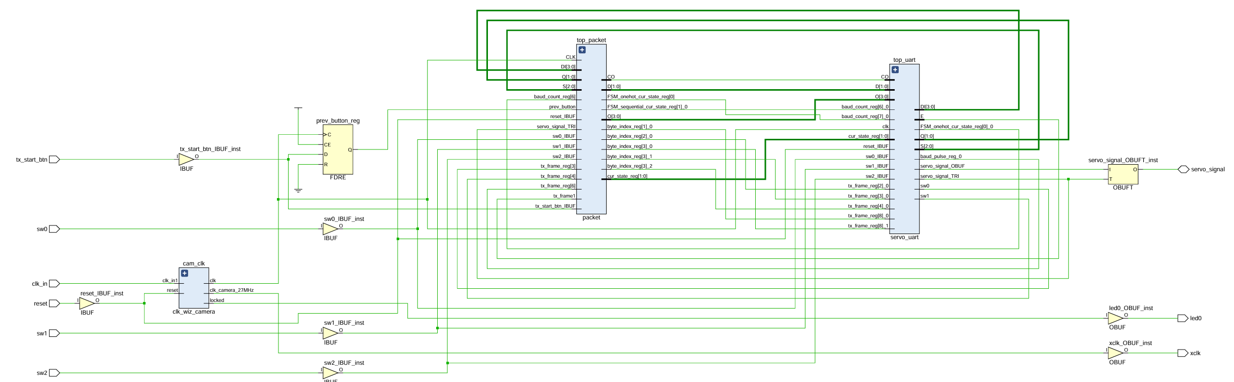 ◢ Elaborated schematic of the packet and UART modules driving the servo line through a tristate buffer
I couldn't just send everything raw at full speed, because the FPGA's clock runs at 100 MHz while the servo's baud rate is 1,000,000 baud.
If you're unfamiliar with UART (Universal Asynchronous Receiver-Transmitter): the "asynchronous" part means there isn't a shared clock between sender and receiver, so they have to agree in advance on a rate they'll both stick to. At 1,000,000 baud, each bit has to hold steady for 1 microsecond to be sampled correctly. At the native 100 MHz clock, a "bit" would only last 10 nanoseconds — about 100 clock edges would fly past within every intended bit period, and the receiver would sample noise instead of a clean 0 or 1.
First Motion
At this point, I wanted to test a sample packet and bound my switches to a few positional values. The servo supports positions 0–4095 (2^12 − 1, the max that fits in 12 bits), so I set a zero, a half, and a full position. I also noticed in the demo that it wouldn't rotate all the way, because the servo arm was interfering with the housing — but you get the point.